Transistor Series Voltage Regulator Experiment . Load current vs output voltage. Web essentially, a series regulator which is also called series pass transistor is a variable resistance created using a. It is also called a series regulator since the control element (transistor) is in series with the load. It uses three transistors, q1, q2 a. In the figure below, you can see a simple series voltage regulator that is using a transistor and zener diode. You can see in the figure that the load current is passing through the series transistor q1 & that’s the reason why we call the circuit a series voltage regulator. • gain experience in making power supply performance. Students construct a power supply using a linear. Web to design and set up a transistor series voltage regulator using bjt and zener diode. Web a simple emitter follower regulator is shown in fig. D q3, and a zener diode. Web transistor series voltage regulator.
from www.slidemake.com
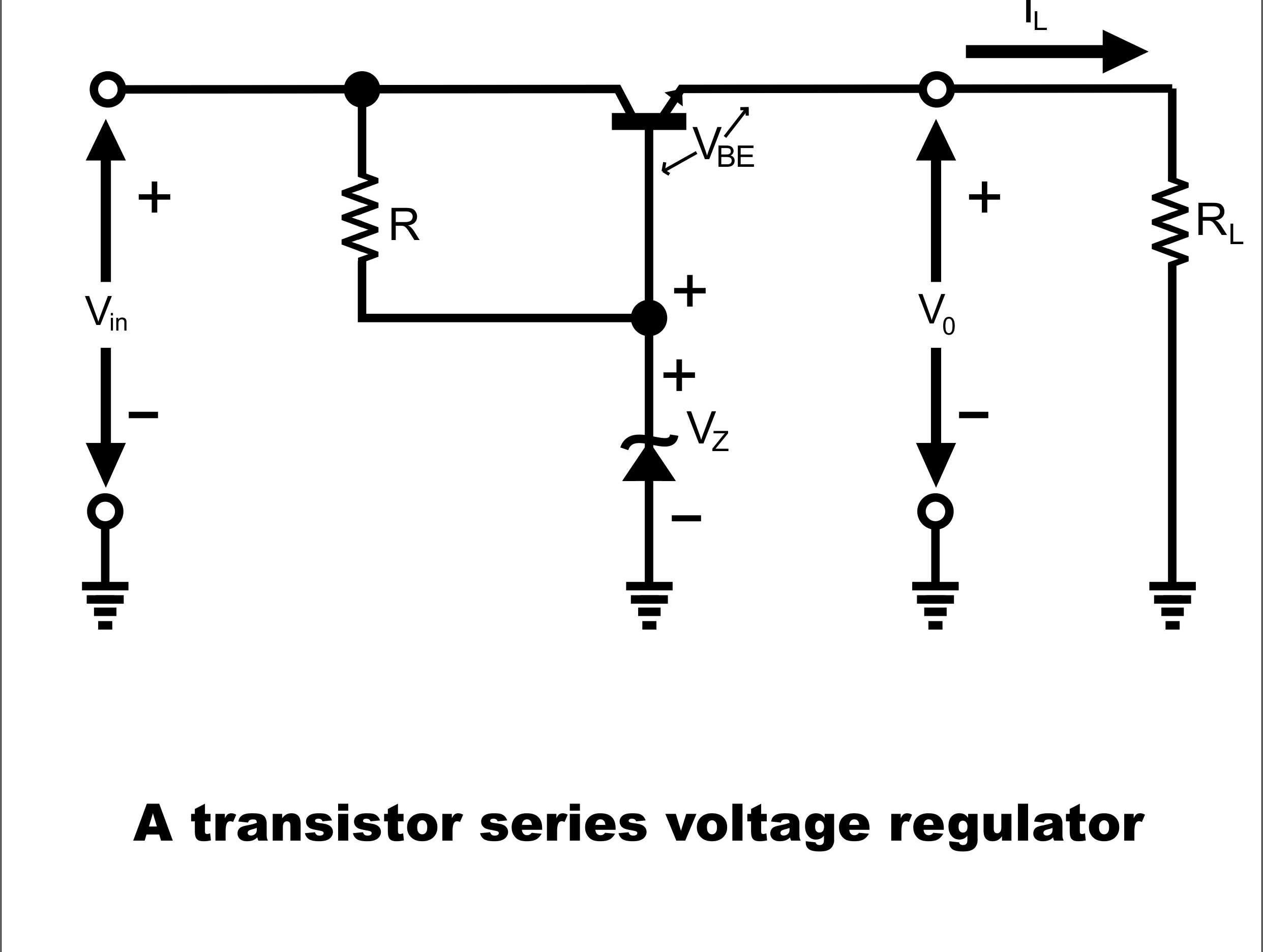
It is also called a series regulator since the control element (transistor) is in series with the load. Web to design and set up a transistor series voltage regulator using bjt and zener diode. It uses three transistors, q1, q2 a. Web transistor series voltage regulator. You can see in the figure that the load current is passing through the series transistor q1 & that’s the reason why we call the circuit a series voltage regulator. • gain experience in making power supply performance. Web a simple emitter follower regulator is shown in fig. Students construct a power supply using a linear. D q3, and a zener diode. Web essentially, a series regulator which is also called series pass transistor is a variable resistance created using a.
Series Voltage Regulator Presentation
Transistor Series Voltage Regulator Experiment D q3, and a zener diode. Web essentially, a series regulator which is also called series pass transistor is a variable resistance created using a. You can see in the figure that the load current is passing through the series transistor q1 & that’s the reason why we call the circuit a series voltage regulator. Load current vs output voltage. Web to design and set up a transistor series voltage regulator using bjt and zener diode. Web transistor series voltage regulator. Web a simple emitter follower regulator is shown in fig. • gain experience in making power supply performance. It is also called a series regulator since the control element (transistor) is in series with the load. Students construct a power supply using a linear. It uses three transistors, q1, q2 a. In the figure below, you can see a simple series voltage regulator that is using a transistor and zener diode. D q3, and a zener diode.
From www.youtube.com
Transistor Series Voltage Regulator, Zener Diode Voltage Regulator Transistor Series Voltage Regulator Experiment It is also called a series regulator since the control element (transistor) is in series with the load. • gain experience in making power supply performance. Web a simple emitter follower regulator is shown in fig. Web essentially, a series regulator which is also called series pass transistor is a variable resistance created using a. Students construct a power supply. Transistor Series Voltage Regulator Experiment.
From schematicdatagrooms123.z5.web.core.windows.net
Series Voltage Regulator Circuit Diagram Transistor Series Voltage Regulator Experiment Web a simple emitter follower regulator is shown in fig. Web transistor series voltage regulator. In the figure below, you can see a simple series voltage regulator that is using a transistor and zener diode. D q3, and a zener diode. • gain experience in making power supply performance. Students construct a power supply using a linear. Web to design. Transistor Series Voltage Regulator Experiment.
From www.youtube.com
Transistor Series Voltage Regulator (हिन्दी ) YouTube Transistor Series Voltage Regulator Experiment Load current vs output voltage. Web essentially, a series regulator which is also called series pass transistor is a variable resistance created using a. It uses three transistors, q1, q2 a. You can see in the figure that the load current is passing through the series transistor q1 & that’s the reason why we call the circuit a series voltage. Transistor Series Voltage Regulator Experiment.
From www.youtube.com
series voltage regulator lab experiment YouTube Transistor Series Voltage Regulator Experiment It uses three transistors, q1, q2 a. In the figure below, you can see a simple series voltage regulator that is using a transistor and zener diode. It is also called a series regulator since the control element (transistor) is in series with the load. Students construct a power supply using a linear. • gain experience in making power supply. Transistor Series Voltage Regulator Experiment.
From www.electroniclinic.com
Series Voltage Regulator and Shunt Voltages Regulator Transistor Series Voltage Regulator Experiment D q3, and a zener diode. • gain experience in making power supply performance. It uses three transistors, q1, q2 a. It is also called a series regulator since the control element (transistor) is in series with the load. Web essentially, a series regulator which is also called series pass transistor is a variable resistance created using a. Web a. Transistor Series Voltage Regulator Experiment.
From electronics.stackexchange.com
Buildint series voltage regulator using transistor and zener diode Transistor Series Voltage Regulator Experiment Web transistor series voltage regulator. You can see in the figure that the load current is passing through the series transistor q1 & that’s the reason why we call the circuit a series voltage regulator. It is also called a series regulator since the control element (transistor) is in series with the load. In the figure below, you can see. Transistor Series Voltage Regulator Experiment.
From www.youtube.com
LT SPICE tutorial 01 Transistor Series Voltage Regulator YouTube Transistor Series Voltage Regulator Experiment It uses three transistors, q1, q2 a. Web essentially, a series regulator which is also called series pass transistor is a variable resistance created using a. Students construct a power supply using a linear. • gain experience in making power supply performance. In the figure below, you can see a simple series voltage regulator that is using a transistor and. Transistor Series Voltage Regulator Experiment.
From wirepartnotaryship.z22.web.core.windows.net
Zener Diode As Voltage Regulator Experiment Circuit Diagram Transistor Series Voltage Regulator Experiment Web to design and set up a transistor series voltage regulator using bjt and zener diode. Load current vs output voltage. Web transistor series voltage regulator. • gain experience in making power supply performance. It uses three transistors, q1, q2 a. Web a simple emitter follower regulator is shown in fig. Web essentially, a series regulator which is also called. Transistor Series Voltage Regulator Experiment.
From www.youtube.com
Powerful 024v Voltage Regulator Circuit Using One Transistor YouTube Transistor Series Voltage Regulator Experiment Students construct a power supply using a linear. D q3, and a zener diode. It uses three transistors, q1, q2 a. In the figure below, you can see a simple series voltage regulator that is using a transistor and zener diode. Web to design and set up a transistor series voltage regulator using bjt and zener diode. It is also. Transistor Series Voltage Regulator Experiment.
From www.homemade-circuits.com
Voltage Regulator Circuits and Projects Homemade Circuit Projects Transistor Series Voltage Regulator Experiment D q3, and a zener diode. You can see in the figure that the load current is passing through the series transistor q1 & that’s the reason why we call the circuit a series voltage regulator. Web a simple emitter follower regulator is shown in fig. It is also called a series regulator since the control element (transistor) is in. Transistor Series Voltage Regulator Experiment.
From www.numerade.com
SOLVED A series voltage regulator circuit in Figure 1 produces an Transistor Series Voltage Regulator Experiment You can see in the figure that the load current is passing through the series transistor q1 & that’s the reason why we call the circuit a series voltage regulator. Web to design and set up a transistor series voltage regulator using bjt and zener diode. It is also called a series regulator since the control element (transistor) is in. Transistor Series Voltage Regulator Experiment.
From www.artofit.org
Creating transistor series voltage regulator circuit Artofit Transistor Series Voltage Regulator Experiment Students construct a power supply using a linear. In the figure below, you can see a simple series voltage regulator that is using a transistor and zener diode. Load current vs output voltage. Web to design and set up a transistor series voltage regulator using bjt and zener diode. It is also called a series regulator since the control element. Transistor Series Voltage Regulator Experiment.
From www.circuitdiagram.co
Draw The Circuit Diagram Of Voltage Regulator Using Zener Diode Transistor Series Voltage Regulator Experiment You can see in the figure that the load current is passing through the series transistor q1 & that’s the reason why we call the circuit a series voltage regulator. Web transistor series voltage regulator. In the figure below, you can see a simple series voltage regulator that is using a transistor and zener diode. Web to design and set. Transistor Series Voltage Regulator Experiment.
From www.youtube.com
LM317 powerful voltage regulator circuit MJE3055 transistor (with Transistor Series Voltage Regulator Experiment You can see in the figure that the load current is passing through the series transistor q1 & that’s the reason why we call the circuit a series voltage regulator. • gain experience in making power supply performance. Load current vs output voltage. D q3, and a zener diode. In the figure below, you can see a simple series voltage. Transistor Series Voltage Regulator Experiment.
From www.youtube.com
Make your own 7805 Voltage Regulator from Transistor How to make 12v Transistor Series Voltage Regulator Experiment It uses three transistors, q1, q2 a. Web to design and set up a transistor series voltage regulator using bjt and zener diode. It is also called a series regulator since the control element (transistor) is in series with the load. In the figure below, you can see a simple series voltage regulator that is using a transistor and zener. Transistor Series Voltage Regulator Experiment.
From www.slidemake.com
Series Voltage Regulator Presentation Transistor Series Voltage Regulator Experiment D q3, and a zener diode. • gain experience in making power supply performance. It uses three transistors, q1, q2 a. Web a simple emitter follower regulator is shown in fig. You can see in the figure that the load current is passing through the series transistor q1 & that’s the reason why we call the circuit a series voltage. Transistor Series Voltage Regulator Experiment.
From www.slideserve.com
PPT Chapter 6 Voltage Regulator PowerPoint Presentation ID5931334 Transistor Series Voltage Regulator Experiment Web a simple emitter follower regulator is shown in fig. Load current vs output voltage. • gain experience in making power supply performance. In the figure below, you can see a simple series voltage regulator that is using a transistor and zener diode. Web to design and set up a transistor series voltage regulator using bjt and zener diode. You. Transistor Series Voltage Regulator Experiment.
From wiredataedwin.z6.web.core.windows.net
Zener Diode As Voltage Regulator Experiment Circuit Diagram Transistor Series Voltage Regulator Experiment Load current vs output voltage. You can see in the figure that the load current is passing through the series transistor q1 & that’s the reason why we call the circuit a series voltage regulator. Web to design and set up a transistor series voltage regulator using bjt and zener diode. In the figure below, you can see a simple. Transistor Series Voltage Regulator Experiment.